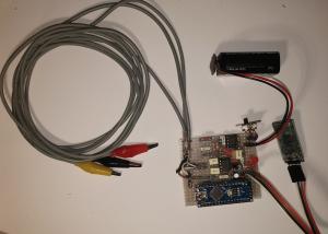
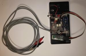
Assembly Manual
This section describes how to realize the hardware circuit. No software programming knowledge is required since all you need is to install the App by opening the apk file from an Android smartphone and to upload the provided Arduino sketch on the Arduino board. However, source files are available to modify or personalize the App (Android programming skills needed) and/or Arduino program (Arduino programming skills needed).
All the files you need and a mode detailed Assembly Manual file are available in the Downloads section.
The ECG device is intended only as a design research project and it is NOT a medical device, so please read the Warnings and safety issues before going on.
Hardware description
The simple circuit design and layout are a good compromise for having both a low cost (few components) and good performance.
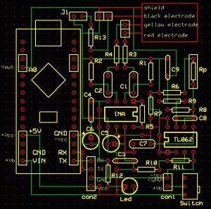
The battery supplies (+Vb) the Arduino board and the led L1 when the device is turned on (R12 = 10 kOhm controls L1 current); the rest of the device is supplied by the Arduino 5 V voltage output (+Vcc). Basically the device works between 0 V (-Vcc) and 5 V (+Vcc), however the single supply is converted to dual supply by a voltage divider with equal resistors (R10 and R11 = 1 MOhm), followed by a unity gain buffer (1/2 TL062). The output has 2.5 V (the mid-voltage of the TL062 power supply: 0-5 V); the positive and the negative rails of power then give a dual supply (± 2.5 V) with respect to the common terminal (reference value).
The capacitors C3 (100 nF), C4 (100 nF), C5 (1 uF, electrolytic) and C6 (1 uF, electrolytic) make the voltage supply more stable.
For safety issue, each electrode is connected to the device through a protection resistor of 560 kOhm (R3, R4, R13) to limit the current flowing into the patient in case of a fault inside the device. These high resistors (R3, R4, R13) should be used against the rare situation when the low voltage power (6 or 9 V, according to the used battery supply voltage) comes directly to the patient leads accidentally, or due to the INA component failing.
Besides, two CR high pass filters (C1-R1 and C2-R2), placed at two inputs, block the dc current and reduce unwanted dc and low-frequency noise generated by contact potentials of electrodes. ECG signal is so high pass filtered before the amplifying stage with a cut off frequency around 0.1 Hz (at -3 dB). The presence of R1 (as R2) reduces the input impendence of the pre-amplification stage so that the signal is reduced by a factor depending on the value of the R1 and R3 (as R2 and R4); such factor can be approximated as:
R1 / (R1 + R3) = 0.797 if R1 = 2.2 MOhm and R2 = 560 kOhm
It is more advisable to choose the couple C1 - C2 (1 uF, film capacitor) with capacity values very close each other, the couple R1- R2 (2.2 MOhm) with resistance values very close each other and the same for the couple R3 - R4. In this way, an unwanted offset is reduced and not amplified by the instrumentation amplifier (INA128). Any mismatch between circuit parameters of the components in the dual input circuit contributes to a degradation of the CMRR; such components should be very well matched (even the physical layout) so that their tolerance should be chosen as low as possible (alternatively the operator can measure their values manually with a multimeter in order to choose the couple components with the values as close as possible).
R5 (2.2 kOhm) defines the INA128 gain according to the formula:
G_INA = 1 + (50 kΩ / R5)
ECG signal is so amplified by the INA and successively high pass filtered by C7 and R7 (with a -3 dB cut off frequency around 0.1 Hz if C7 = 1 uF and R7 = 2.2 MOhm) to eliminate any dc offset voltage before the last and higher amplification made by the operation amplifier (1/2 TL062) in a non-inverting configuration with a gain:
G_TL062 = 1 + (R8 / (Rp+R6))
To let the user change the gain at runtime, the operator can choose to use a variable resistor (trimmer / potentiometer) instead of Rp or a female socket strip for a resistor that can be changeable (because not soldered). However, in the first case it is not possible to know exactly the actually gain of the ECG signal (the values in mV of the data will be not correct) while in the second case it is possible to have the correct values in mV by specifying the value of Rp in the formula “Gain” inside the “Setting” section of the app (see User Manual).
C8 capacitor creates a low pass filter with a -3 dB cut off frequency around 40 Hz as the RC filter composed by R9 and C9. The cut-off frequency value is given by the formula:
f= 1 / (2*π*C*R).
For low pass filters @ 40 Hz [1], RC components values are:
R8 = 120 kOhm , C8 = 33 nF , R9 = 39 kOhm , C9 = 100 nF
The ECG signal is so filtered in a band between 0.1 and 40 Hz and amplified with a gain equal to:
Gain = 0.797 * G_INA * G_TL062
Since R5 = 2,2 kOhm , R8=120 kOhm, R6=100 Ohm, Rp=2,2 KOhm ,
Gain = 0.797 * (1+50000 / 2200) * (1+120000 / (2200 + 100)) = 1005
To have accurate values for the filter cut-off frequencies, RC filter components should have a tolerance as low as possible (alternatively the operator can measure their values manually with a multimeter in order to choose the ones closest to the desired value).
The analog signal is digitalized by the Arduino board (A0 input channel) and then transmitted to the HC-06 module by the serial communication pins; finally, the data are sent to the smartphone by Bluetooth.
The reference electrode (black) is optional and can be excluded by removing the jumper J1 (or the operator can use a switch instead of the jumper). The circuit configuration is designed to work also with two electrodes; however, the reference electrode should be used to have a better signal quality (lower noise).
Components
By excluding the Smartphone and disposable parts (electrodes and batteries), the whole device cost is around 43 US dollars (here considered the single product; in case of a larger quantity, the price would go down).
For a detailed list of the all the components (description and approximate costs), please see Assembly Manual file available in the Downloads section.
How to build
- Need Tools: tester, clippers, soldering iron, solder wire, screwdriver and pliers.
- Prepare a perforated prototype board with 23x21 holes (around 62 mm x 55 mm)
- According to the PCB top layout, solder: resistors, connecting wires, female socket strip (for Rp)
sockets, male and female header connectors (female header connectors position here reported in the figures is suitable for Arduino Nano or Arduino Micro), capacitors, Led
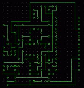
- Connect all components according to the PCB bottom layout
- Realize a wire connector for the battery using the battery strap/holder, female header connectors and heat shrink tubing; connect it to the PCB “con1” (connector1)
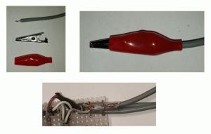
- Realize three electrodes cables (using the coaxial cable, female header connectors, heat shrink tubing, alligator clip) and connect them to the PCB tightening them to the board with some rigid cables
- Realize a switch (using the slide switch, female header connectors, heat shrink tubing) and connect it to the PCB
- Place the INA128, TL062 and Rp resistor into the correspondent sockets
- Program (see Software Description section) and connect the Arduino Nano board (perforated prototype board and female header connectors should be adjusted on the PCB if another Arduino board (e.g. UNO or Nano) is used)
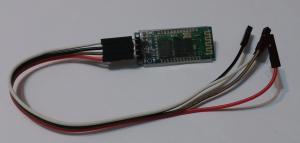
- Connect the HC-06 module to PCB “con2” (connector2)
- Connect the jumper J1 to use the reference electrode
- Connect the battery
- Place the circuit inside a suitable box with holes for the Led, the cables and the switch.
A more detailed description is shown in the Assembly Manual file available in the Downloads section.
Other options
- The ECG signal for monitoring application is filtered between 0.1 and 40 Hz; the upper band limit of the low pass filter can be increased by changing R8 or C8 and R9 or C9.
- Instead of the Rp resistor, a trimmer or potentiometer can be used to change the gain (and amplify the ECG signal) at runtime.
- The ECG device can work also with different Arduino boards. Arduino Nano and Arduino UNO were tested. Other boards can be used (such as Arduino Micro, Arduino Mega, etc.) however the provided Arduino sketch file needs modifications according to the board features.
- The ECG device can work also with the HC-05 module instead of HC-06 one.
Software Description
No software programming knowledge is required.
Arduino Programming: Arduino sketch files can be uploaded on the Arduino board easily by installing the Arduino Software IDE (free download from the Arduino official website) and following the tutorial available on Arduino official web site. A single sketch file (“ECG_SmartApp_skecht_arduino.ino”) for both Arduino Nano and Arduino UNO is provided in the Downloads section (the sketch was tested with both the boards). The same sketch should work also with Arduino Micro (this board was not tested). For other Arduino board, the sketch file may need changes.
Installing the ECG SmartApp: To install the App, copy the provided apk file “ECG_SmartApp.apk” in the Downloads section (or “ECG_SmartApp_upTo150Hz.apk” in case of the version for bandwidth at 150 Hz) on the smartphone memory, open it and follow the instruction by accepting the permissions. Before installing, it may be needed to change the smartphone setting by allowing installation of app from unknown sources (tick the box of “Unknown sources” option of the “Security” menu). To connect the ECG device with the HC-06 (or HC-05) Bluetooth Module, pairing code or password may be asked in case of the first Bluetooth connection with the module: enter “1234”. If the App does not find the Bluetooth Module, try to pair the smartphone with the HC-06 (or HC-05) Bluetooth Module by using the smartphone Bluetooth Setting (pairing code “1234”); this operation is needed only once (first connection).
Source files are available in the Downloads section to modify or personalize the App. However, Android programming skills are needed.


