HARDWARE
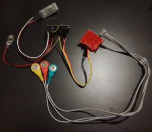
The ECG SmartApp device can be built easily (in less than 1 hour by following the Assembly Manual) and only a very basic electronics skills are needed. The device is battery powered and consists of a front-end circuit (ECG module AD8232) to acquire the ECG signals (limb leads only) through common electrodes and an Arduino board to digitalize the analog signal and transmit it to an Android smartphone via Bluetooth protocol.
COMPONENTS
By excluding the Smartphone and disposable parts (electrodes and batteries), the device whole cost is between 20 and 25 Euros (25-30 US dollars).
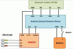
The hardware can be easily obtained by assembling the three needed modules as shown in the scheme. Here all the components needed:
- ECG module AD8232 (Module Single-Lead, Heart Rate Monitor Front End) + electrodes cable (usually already included in the off the shelf module)
- Arduino Nano board
- HC-05 (or HC-06) Bluetooth module
- Battery holder/clip
- Switch
- Box
- Connector cables / wires
Connections can be made by soldering wires directly to the boards or using connector cables with female headers. The battery supplies the Arduino board; HC-06 (or HC-05) module is supplied by the Arduino 5 V voltage output while AD8232 module is supplied by the Arduino 3.3 V voltage output.
SOFTWARE
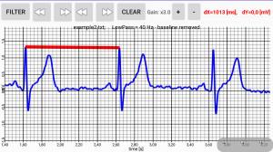
The related App visualizes the ECG signal in real time and gives the possibility to filter, make measurements (with a caliper function) and store the signal in a file.
No software programming knowledge is required since all you need is to install the App by opening the apk file from an Andriod smartphone and to upload the provided Arduino sketch on the Arduino board (this can be done easily by using the Arduino Software IDE and one of the many tutorials available on the web).
Arduino Programming
Arduino sketch files can be uploaded on the Arduino board easily by installing the Arduino Software IDE (free download from the Arduino official web site) and following the tutorial available on Arduino official web site. A single sketch file (“ECG_SmartApp_skecht_arduino.ino”) for both Arduino Nano and Arduino UNO is provided (the sketch was tested with both the boards). The same sketch should work also with Arduino Micro (this board was not tested). For other Arduino board the sketch file may need changes.
Installing the ECG SmartApp on your Android mobile
To install the App, copy the provided apk file “ECG_SmartApp_Ver3.apk” on the smartphone memory, open it and follow the instruction by accepting the permissions. Before installing, it may be needed to change the smartphone setting by allowing installation of app from unknown sources (tick the box of “Unknown sources” option of the “Security” menu). To connect the ECG device with the HC-06 (or HC-05) Bluetooth Module, pairing code or password may be asked in case of the first Bluetooth connection with the module: enter “1234”. If the App does not find the Bluetooth Module, try to pair the smartphone with the HC-06 (or HC-05) Bluetooth Module by using the smartphone Bluetooth Setting (pairing code “1234”); this operation is needed only once (first connection)
EcgSmartApp is available only for Android (at least Android 6 or higher).
Additional RLD resistor for safety issue
For safety issue, RLD output is connected to the electrode through a protection resistor. Off the shelf AD8232 modules usually uses a 360 kOhm resistor in series with the RLD output since its supply is 3.3V. Even if the AD8232 module is powered by the Arduino at 3.3 V, in the worst-case failure, the battery voltage value should be considered. So, if a 6V (or 9V) battery is used, to keep the RLD current limit lower than 10 uA, a 680 kOhm resistor (or 1 MOhm) is needed (current = voltage / resistance). So, the 360 kOhm resistor needs to be replaced. This operation is the only one requiring some soldering skill since such resistors (SMD) are very small. More details and alternative solutions are described in the Assembly Manual.
Electrodes
Off the shelf AD8232 modules usually includes the electrodes cable that can be plugged in the boards directly through the dedicated connector. However, it is possible to make a customized electrodes cable and to connect it to the dedicated pins of AD8332. The cable can be realized by using a coaxial cable (better if shielded, to reduce external noise), alligator clip, heat shrink tubing and female header connectors.
Note about power supply
The device must be powered only by batteries and the voltage value must be between 6 and 9 V. The minimum voltage supply recommended for the Arduino nano is 7 V however if the batteries are full charged, the device is able to work fine at 6 V (e.g. 4 x 1.5 V AA batteries full charged or 5 x 1.2 V AA rechargeable batteries full charged). If operating at 6 V, the acquired ECG signal may become quite noisy when the batteries becomes to discharge. Using voltage value higher than 6 V (e.g. a 9 V battery) can avoid this issue.
Other Arduino Boards
The ECG device can work also with different Arduino boards. Arduino Nano and Arduino UNO were tested. Other boards can be used (such as Arduino Micro, Arduino Mega, ect.) however the provided Arduino sketch file needs modifications according to the board features.
The ECG device can work also with the HC-05 module instead of HC-06 one.
HARDWARE SPECIFICATIONS
For detailed specifications, see the User Manual.
Through the electrodes, the ECG signal is amplified by the AD8232 modules.
AD8232 modules available on the market usually have a configuration of resistors and capacitors that give a frequency band between 0.5 and 40 Hz and an overall gain of 1100.
After amplified and filtered by the AD8232 stage, the ECG signal (still analog signal) is digitalized by the Arduino board (A0 input channel @ 600 Hz and 10 bits resolution on a full scale fo 3.3 V) and then transmitted to the HC-06 module by the serial communication pins; finally the data are sent to the smartphone by Bluetooth.
Voltage supply:
USE ONLY BATTERIES
Min Voltage supply: 6V (e.g. 4 x 1.5V batteries)
Max Voltage supply: 9V (e.g. 6 x 1.5V or 1 x 9V batteries)


